![]()
![]()
![]()
|
|
TROLLEY AS COST EFFICIENT TRANSIT by Rick Zimmerman From the Electric Railroads chapter by Wm. A. Delmar in Mansfield Merriam's American Civil Engineers' Handbook, 1920, 4th edition.
As the 1920's opened, the electric railroad (street cars or trolleys) had a virtual monopoly for street and inter-urban mass transportation systems because of its energy efficient use. The power to drive the train was concentrated in a single central plant.
Coal provided a common denominator for efficiency comparisons. Even though electric power required a larger initial capital expenditure, electric traction required having the amount of coal per car needed with steam traction. Nearby water power for electric generation often made the electric power for mass transit a certainty for lower costs.
The layout surveyed for an electric trolley line had a direct bearing on its prospects for economic success. A curve always gives rise to a retarding force in the train, increasing operating costs, and slowing timetables. Each degree of curvature was taken as an equivalent to an up grade of 0.05%.
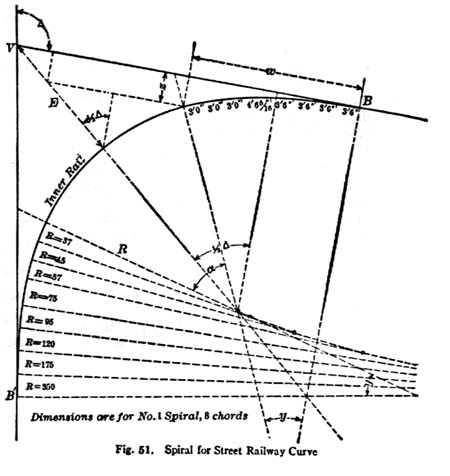
For easy curves, spirals (or transition curves) were borrowed directly from those in general use for steam railway work (see Merriam's chapter on Steam Railroads). However, curves around street corners were usually so sharp that "special work" spirals had to be generated, allowing for more rapid changes of curvature. These were applied in trolley line layouts as branch-offs, Y's, as well as approaches to single curves.
The critical items required from the engineer were: (a) the total central angle of the curve, (b) the total required clearance of center of curve between curb and nearest rail and (c) the distance from rails to curb in each street. Spacing between track centers for double track or turnouts depended not only on overall car width, but also on the speed of the cars traveling through the curve.
Applying this system, switches could be set into the plain ends of curves without changing the lines. The curves in the table are those of the inner rail gage line, not the center line of the track as in steam railway work. Merriams's also used Wharton's system for selecting a curve with spirals, for example, to lay out a track inside a curving parallel highway.
A system to determine spacing of turnouts on single track roads is included in the fourth edition of Merriam's. Here, variables are reduced to a common time denominator: number of trains, engines per train, number of cars per train, grades along legs of the road, excessive curvature, and speed in populated areas. All of these increase time in the same way that distance does. Location of the turnouts is determined graphically by scaling off a worksheet.
Trolleys may yet again be cost effective alternatives to private transportation as the cost of gasoline goes up, and electric costs come down.
|
|
|