![]()
![]()
![]()
|
|
|
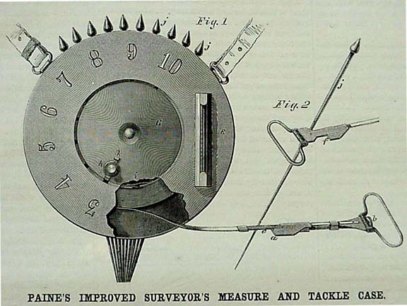
The following article is taken from the publication Scientific American circa 1861 Improved Surveyor's Measure and Tackle Case
The apparatus embraces two distinct inventions, one consisting of a light, narrow steel tape, in combination with its removable and adjustable handles, and the other, of the case in which the tape is wound and carried. The measuring tape is of a low spring temper, and is covered with a coating of tin to protect it from rust; it is graded and marked in chain and links, or otherwise, as desired. The handles are removable, and are fastened to the ends of the chain in the manner clearly shown in Fig. 1, in the cut. The end of the tape is slipped under the clasps of the handle, when a small hole near its end slips over a short pin fixed rigidly to the handle; the spring of the tape holding it down upon the pin. As the length of the tape is varied by the changes of temperature, an arrangement is made for adjusting the measuring part of the tape to compensate for the expansions and contractions. The shoulder, a, on one of the handles is formed upon a movable piece of metal which is caused to slide back and forth along the graduated scale, c, by turning the tangent screw, b. By careful measurement of the tape at the manufactory, at different temperatures, the point indicating the desired length of measure is ascertained and marked on the scale, c, with the corresponding degree of temperature. Then, at any time when it is desired to use the measure, by observing the temperature of the atmosphere as indicated by the thermometer, E, attached to the tape case, and adjusting the shoulder, a, to the corresponding figure marked upon the scale, c, a measure of uniform length is preserved, notwithstanding the expansions and contractions of the metal resulting from the varying temperature of the season or the day. The handle, Fig. 2, at the opposite end of the tape, has its shoulder, f, formed to come against the same side of the pin as shoulder, a, thus securing the utmost accuracy in the starting points from each station. When the work is done the handles are removed and the tape is coiled into the case represented in Fig. 1. This may be a thin brass box, similar to an ordinary tape box. The central plate, G, is made to revolve about the central pivot, a knob, k, serving as a handle to turn it. A flange is turned up on the edge of the plate, G, for the tape to wind around, and a simple arrangement is made for gripping and holding the end of the tape which is first pushed in the case. A small slot is cut through the flange, and opposite this is secured a small steel spring, i, which, as the end of the tape is pushed under it, presses down and holds the end secure. In order that the tape may enter the slot in the flange, it is necessary that the plate, G, should be turned in the proper position, which is easily indicated by the position of the knob, h. The case serves as a convenient quiver for carrying the pins, j, and each time the ten are exhausted, the "out" is marked by turning the plate, G, so that the knob, h, will pass forward one figure to the next, and thus the tally is kept in the safest manner possible. A slot is cut in the case opposite each figure for the entrance of the bolt, k, which holds the plate, G, securely in position until it is desired to turn it forward. The extreme lightness of this tape enables it to be drawn almost perfectly straight with a very slight strain; the compensating arrangement for variations of temperature is exceedingly simple, convenient and accurate; the case preserves the records of the measure in a manner well calculated to insure correctness; and the whole apparatus is certainly the best surveyor's measure that we have ever examined. It has met the decided approval of the most eminent engineers in the country, including that of Professor Bache, of the Coast Survey. The patent for this invention was granted, through the Scientific American Patent Agency, July 10, 1860, and communications in relation to the instruments, or rights for the manufacture or sale of the same should be addressed to the inventor, W. H. Paine, Sheboygan, Wisconsin.
|
|
|