
![]()
![]()
|
|
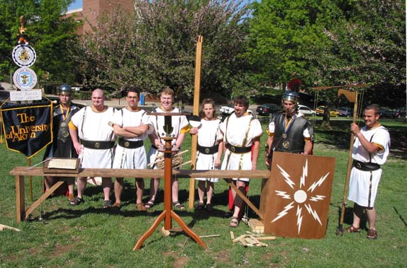
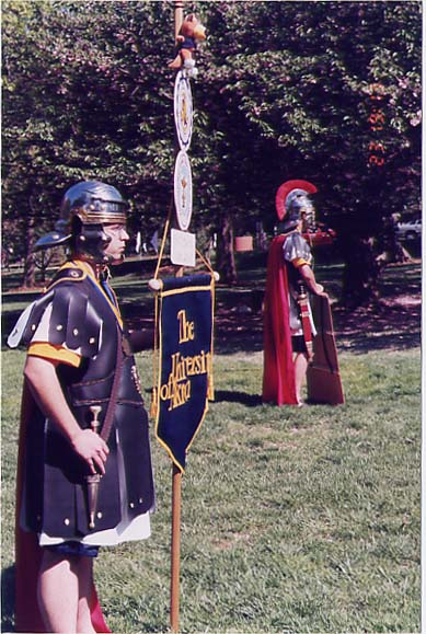
THE ANALYSIS AND APPLICATIONS OF ROMAN SURVEYING TOOLS AND METHODS Compiled by: The University of Akron - Surveying and Mapping Technology Roman Surveying Team
INTRODUCTION
The instruments and methods employed by present-day surveyors are not simply the product of the fertile imagination of a few smart minds confined to a "think tank". These tools and methods evolved over the course of many hundreds, even thousands of years. Early measurement units, originally based on the lengths of certain body parts of the ruler, were eventually standardized. Surveying instruments and methods were, and still are today, constantly being refined in the field.
The first evidence of land surveying comes from the early days of the Babylonian empire. The humble principles of basic land measurement used by the Babylonians evolved into the standard measuring tools and mathematical processes developed by the Egyptians. The Greeks further refined the mathematics and enhanced the tools used by the Egyptians. When the Roman Empire came into being, they adapted much in the way of Greek culture, including their methods of surveying. While many sources tend to believe that the Romans chose to ignore many of the higher Greek theories in mathematics, they did improve upon the instrumentation and implementation of those tools to their way of carving their empire. It is this unique historical time frame that has been selected as part of satisfying the requirements for the Roman survey competition.
The primary tools and methods used by the agrimensores (literally "land measurers") of the ancient world can be divided into three main categories: horizontal angles, vertical angles/elevation and linear distance measurements. These three categories will be discussed in this order. Evidence of creation and use, as referenced in the research, will be presented, followed by the students' recreation and derivation of use based upon the research.
The intent of this paper is to accurately portray the following concepts: the appropriate means and methods, based on the historical collaboration of research, of the Roman agrimensores; the means and methods that the University of Akron student survey team will adopt, based upon the preponderance of evidence found in the research, as the primary means of accurately replicating the field work of the agrimensores. Also included in this paper are various units, conversions to modern units of measure and terminology of the agrimensores.
HORIZONTAL ANGLE MEASUREMENT
The first category to be discussed is in the area of angular measurement. According to various sources, tow primary instruments rose above the rest as the approved angle-measuring tools of the day: the groma and the more sophisticated dioptra.
The Groma
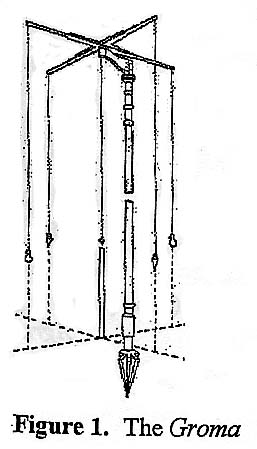
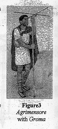
The groma (pronounced "grow-mah"), or "cross-staff," was the principal layout tool of the agrimensores (See Figure 1 and Figure 2). The primary usages of this instrument were to layout straight lines and right angles. Amazingly, agrimensores and engineers of the day were able to create elaborate cities and encampments, despite its relative simplicity! The groma was also used to geometrically divide plots of land, termed "centuriation." Areas of field were measured by laying out two right-angle lines, joining their extremities by straight lines and finding their perpendicular offsets from these to the irregular sides, thus, creating the divided plot of land.
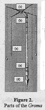
This instrument was made of several different parts (See Figure 1). It was composed of a supporting rod (a), a rotating arm (b), a cross staff (c), and an iron shoe (d). Simple fittings and screws hold these parts together. From the cross staff hung two pairs of plumb bobs (e), one pair resembling a pear-like shape and the other pair tapering to a point. A fifth plumb bob was believed to have hung from the intersection at the center of the cross (Figure 2). This plumb bob would have been oriented over the designated point of control. During unfavorable weather conditions, such as windy days, the tips of the plumb bob were dipped in water in order to steady the plumb lines.
This instrument was set up by first striking the lower part of the rod into the ground. It was placed at a known distance from the control point so that the center of the cross staff could be aligned over the mark by turning the rotating arms. The agrimensore would then sight beside the two plumb lines suspended from the end of the cross to coincide with the center plumb line (See Figure 3). He would orient where the distant mark or marker would be placed. The same procedure would be performed on the other set of lines, which would create the right angle. This method produced the basic geometry for two main roads, which intersected at right angles to each other, in a typical Roman city or encampment.
Although being a very basic tool, right-angle measurements were created accurately and precisely by the agrimensore. These processes were used to layout much of the Roman Empire, including roads, land tracts and buildings.
Gathering from the evidence of research, this is the method by which the groma was constructed. The staff was approximately six to seven feet tall. The bottom of the staff was fitted with a pointed shoe, approximately 8" in length. This shoe consisted of four large flukes. These flukes protruded from the iron shoe two and one-half inches in radial fashion. The top of the staff was fixed with a swivel peg so that a bracket could rotate around the staff. This bracket was about ten inches long and attached the cross to the staff. This allowed for the cross to be offset, so that the staff would not interfere with sighting. It was made of wood with metal strips wrapped around its top and bottom exterior limits. At one end, the metal supports fastened to a bronze socket, which pivoted on the swivel peg at the top of the staff. At the same end, on the bottom, was a place to attach a plumb bob.
The cross was made of two 36" wooden arms that perpendicularly intersected each other at their respective midpoints. This created a cross with 4-18" radial arms extending every 90 degrees. An angle bracket was attached to the center to hold the arms true to 90 degrees. At the ends of the arms were metal supports. In the center of the cross was a bronze socket, which rotated on the swivel peg that is fixed to the bracket. At the end of each arm hangs a single plumb bob, with each plumb bob measuring eighty centimeters from its counterpart at the other end of the arm.
The Dioptra
The dioptra (pronounced "die-op-treh") was the total station of the Roman Empire. It could be used as a level, a distance-measuring device, or an angle-measuring instrument. The dioptra consisted of four basic parts: the cylindrical base, a graduated rod, a removable angle-measuring disc, and a removable water level. The Romans inherited the dioptra from the Greeks. The rank-and-file of the agrimensores, who preferred simple instruments to complex ones, did not use the dioptra very often. Since the dioptra was a much more accurate instrument than the groma (detailed previously) or the chorobates (discussed later), it makes sense to assume that the Roman engineer used the dioptra when laying out huge projects, such as the aqueducts, that required accurate measurements for thirty, forty, fifty, or more miles.
There were many versions of the dioptra, ranging from simple to complex. One version of the dioptra was that of Hero of Alexandria. His version was relatively complex. Hero lived around 62 A.D., and was a member of the mechanical school of Alexandria. Unlike most Greeks, Hero was down-to-earth, and was not concerned with being an inventor, or an original thinker. Complex theories did not interest him. The dioptra did interest Hero, which led him to write a treatise on the dioptra, in which he discusses how it was built and used (Lewis, 53)
The treatise begins by describing the many uses of the dioptra, which include "laying out aqueducts and walls and harbours and every sort of structure; it greatly benefits observation of the heavens by measuring the distances between stars, and the study of the size, distances and eclipses of sun and moon; likewise geography, by measuring, on the basis of distance, islands and seas and every kind of interval between them." (Lewis, 259). Hero mentions that the dioptra can be used to obtain accurate measurements while maintaining a distance safe from enemy bowshots.
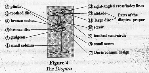
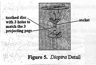
Hero goes on to describe how the dioptra was constructed (Figure 4). He says "There is a stand like a small column (1), with a round gudgeon (the part of the shaft that turns with a bearing or gear) (2), on top around which fits a concentric bronze disc (3). A bronze socket (4) also fits loosely over the gudgeon, free to revolve around it, and has attached to its underside a toothed disc (5), smaller than the disc previously mentioned and resting on it. At its top, the socket ends in a plinth (6) (a square block at the base of, or in this case at the top of, a column, designed for the sake of appearance, like the capital of a Doric column (7). There engages with toothed disc a small screw (8) whose thread fits the teeth of the disc, and the screw's bearings are fixed to the larger disc. So if we turn the screw, we also turn the toothed disc and the socket, which is attached to it by three pins projected from its base and fitting into the disc itself (Figure 5). The screw has along its length a groove as wide as the tread is deep. If then, we turn the screw until the groove corresponds with the teeth on the disc, the disc can be turned by itself. So when we have set it as occasion demands, we will turn the screw a little so that the thread engages the teeth and the disk therefore remains immovable." (Lewis, 260)
Some of the folios (pages) to this treatise are missing, so the description is incomplete. M. J. T. Lewis, in his book Surveying Instruments of Greece and Rome, continues the description of the dioptra. He writes "A toothed semicircle (9), adjusted in a vertical plane by the last-mentioned screw (10), carried the dioptra proper. This comprised a large disc (11), which could be set in the required plane by means of the toothed semicircle, and alidade (12), which rotated on a pivot. To measure angles for astronomical purposes, this plane might lie anywhere between the vertical and horizontal; but for terrestrial use the disc was normally set in a more or less horizontal plane for laying out right angles. For this purpose a right-angled cross (13) was engraved on the disc, with which the alidade could be aligned in either direction." (Lewis 260-261). E. Lancaster-Jones, in the book Catalogue of the Collections In The Science Museum, further describes the dioptra as "consisting of a rotatable sight-rule (the alidade), which could be successively directed in two mutually perpendicular directions defined by stops or index lines (13). For astronomical purposes, such as latitude determinations, the circular plate (dioptra proper) was graduated in degrees." (Lancaster-Jones, 53). For uses other than astronomical, angles were not measured in degrees (Lewis, 51).
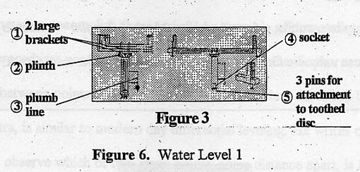
Lewis then goes on to state what he believes Hero wrote about the water level (Figure 6). He writes its, "Instead of the socket carrying the plinth shaped like a Doric capital and the dioptra proper, another socket (1) carries a plinth (2)....on which are mounted two large brackets with vertical flanges (3). It has a plumb line (4) to ensure that it stands vertically. This socket, like the first one, is attached to the toothed disc by three downward-projecting pins (5)." (Lewis, 261). The water level (Figure 4) had a horizontal tube (1) that was finished at both ends with glass (2). The water level also had two screws (3), both connected to a transverse bar (4), each of which raised a plate (5) with slits (6), which serve as the sight. Since water seeks own level, each screw was turned until the slits in the plates matched the level of the water in the glass-ended tube.
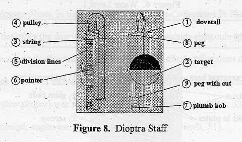
Hero also describes the staff used with the dioptra (Figure 8). There were 2 staves, each 10 cubits long (1 cubit = 18 inches), 5 dactyls wide (1 dactyl = 0.75 inches, 24 dactyls = 1 cubit), and 3 dactyls thick. Down the center of the whole staff is a dovetail (1) (Lewis, xix). A small piece (a cursor) is fitted to slide freely along the inside of the dovetail, to which a target (2) is attached. This target is a flat circular disc about 10-12 dactyls in diameter.
This target can be weighted down with lead weights. Across the center of the target, and perpendicular to the staff, a straight line is drawn to divide the target into equal semicircles. One semi-circle is painted white, and the other black. A thick string (3) is attached to the cursor, which runs over a pulley (4) on the top of the rod, and then goes down the back of the rod. The target then can be moved up and down the rod as needed by pulling or letting out the string. The purpose of this target was to allow the surveyor to be able to sight a precise point on the staff from far away (since optics were not available at this time, the surveyor needed something big that could be seen from a distance to sight on). The staff was divided from the bottom up into cubits, palms (1 palm = 3 inches, 1 palm = 4 dactyls), and dactyls (Lewis, xix). These units are Greek units. Hero and his dioptra were Greek. The Romans inherited the Greek dioptra and did not change much about it, except for changing the units on the dioptra and staff to Roman units. Lines (5) were inscribed into the staff, to the right of the target, showing these divisions. A pointer (6) was attached to the center of the backside of the target to coincide with the graduations on the staff. A plumb bob (7) was attached to the ungraduated side of the target to ensure that the user held the staff plumb. The plumb bob was suspended near the top of the rod from a peg (8) about three dactyls long, which had a hole through it for string to go through. Close to the bottom of the staff was a second peg (9) of the same length, which had a vertical line cut through its center. When the plumb-bob string fell into the vertical cut on the lower peg, the staff was known to be standing vertical.
Use of the Dioptra
Now the dioptra has been fully described. As mentioned earlier, the dioptra could be used as a level, a distance-measuring device, or an angle-measuring instrument. Just how was the dioptra used to accomplish these tasks? An example of how each task was performed will clarify the procedures used by the Romans. When using the dioptra as a level, elevation differences between points can be calculated. The procedure described by Hero, in his treatise on the dioptra, is similar to modern day differential leveling. He writes on how to use the dioptra "To observe which of two given points, some distance apart, is higher or lower and by how much, or if both lie at the same height in a horizontal plane; and to observe how any intermediate points relate to each other and to the original points." (Lewis, 263). Suppose you wanted to move water across the land (Figure 9), which the Romans very often did. There is water at point B, and point A is where you want the water to go.
The first thing to be determined is which point is higher in elevation. One staff (Staff 1) would be held plumb over point A. The staff at point A must remain visible to the surveyor standing at the dioptra. The water level would then be turned until is was sighted on Staff 1. The water level would then be leveled by turning its screws until the attached plates matched the water level. The target on staff 1 is then raised or lowered until its centerline (where the black and which semicircles meet) is in line with the slits in the plates (the sight). The surveyor would then move around to the other side of the dioptra, without moving it, and sight Staff 2, that had been set up at a distance so that is could still be seen from the location of the dioptra. The target on Staff 2 is adjusted at sighted on just as the target on Staff 1 was. Suppose we call the place where the dioptra is set up (C), the place where Staff 2 is set up (D), the height taken off Staff 1 (E), and the height taken off Staff 2 (F). Height E was found to be 8 cubits, and elevation F was found to be 4 cubits. Now two columns are made in the notes, one labeled "Back sights" and the other labeled "Fore sights". The reading from Staff 1 (8 cubits) would be recorded under the Back sight column, and the reading from Staff 2 (4 cubits) would be recorded under the Fore sights column. Leaving Staff 2 at (D), the dioptra was moved forward to (G). Staff 2 is then sighted through the level and Staff 1 is placed ahead of the dioptra, at (H). Without moving the dioptra, Staff 1 is then sighted again. The height on Staff 2 (still located at (D)) was read as 6 cubits, and the height on Staff 1 (located at (H)) was read as 8 cubits. These values were then recorded in the appropriate columns. This process is repeated until the endpoint, B, is reached. The final staff placement should be located right on the surface of the water. The back sight and fore sight columns would be totaled. Because the back sight column total is greater than the fore sight total, point A is found to be lower than point B, and the water would run in the desired direction. If the two totals were the same, then points A and B would be at the same. If the back sight total had been smaller than the fore sight total, the water would not run in the desired direction, and would need to be raised. The elevation of the terrain in between points A and B was now also known, and the water could be directed as needed. (Lewis, 263-265)
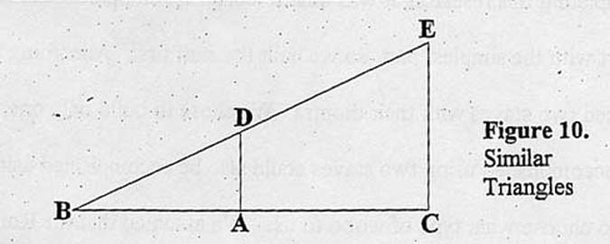
The dioptra was also used to determine distances and angles. A way of determining distances was by using the properties of similar triangles. This can be demonstrated by using another example from Hero's treatise. The dioptra was set up at point (A) (Figure 10). The alidade was rotated until a second point, point (B), was sighted. Then the surveyor would move around to the other side of the alidade, and sight through it another point, point (C). Points (A), (B), and (C) formed a straight line. Then, with the dioptra still on point (A), a right angle was laid out, and a point selected for an end point, in this case, point (D). The right angle was laid out by turning the alidade ninety degrees from line BAC, in the same manner as line AD was laid out. Next, the dioptra was moved to point (E) and point (B) was sighted on. The point where line BE and line AD crossed was marked, in this case as point (D). This procedure resulted in two triangles being laid out: triangles BCE and BAD. Now similar triangle proportions could be established. Line Ad is to line CE, as line BC is to line BA. The ratio of line CE to line AD can be found by actually measuring them. If, for example, line CE is found to be five times longer than line AD, then it is known that line BC was five times longer than line BA. A surveyor could have also measured line AC, and by comparison, could have determined the length of line BA.
Construction of the University of Akron Dioptra
The construction and procedures used for the dioptra have now been clearly spelled out. After completing this research, it was time to construct an operational dioptra. We decided to start with the simplest part, so we built the staff first. According to our research, the Romans used two staves with their dioptra. We chose to build only one, since everything that could be accomplished using two staves could also be accomplished using one. Our first decision was to choose what type of wood to use. We assumed that the Roman surveyor would have wanted his wooden instruments made out of wood that would not swell, thus changing length, in wet or humid weather. After talking with several carpenters, we chose to use redwood. This choice was based on many different factors, among which were: 1. Redwood does not swell up too badly when in humid and/or wet conditions.; 2. Redwood is a relatively lightweight wood, which would make carrying the dioptra and the staff easier.; 3. Redwood is attractive to look at.; 4. Redwood is not too expensive, and is of better quality than cheaper woods such as pine.
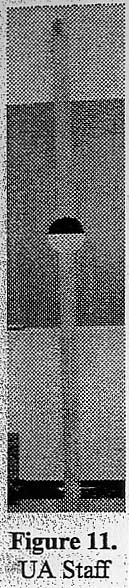
We built our staff to look and work the same way the Roman staff discussed earlier did (Figure 8). Our staff differed from the Hero's staff in two ways. First, our staff is 1-1/2 inches thick, 3 inches wide, and eight feet long. Second, we graduated our staff in Roman feet (1 Roman foot = 296 mm, or 0.97 English feet). Like Hero's staff, these graduations appear on one side of the rod. In all other ways, we came as close to Hero's staff as possible. Our staff contains a dovetail, a cursor, and a flat target. Our target is divided into two equal semi-circles, one of which is painted black, the other is painted white. Our target is weighted with 2 ounces of lead to help it move up and down the staff. On the back of our target, along with the lead weights, a copper arrow points to the correct rod, to pull the target up and down. A lead plumb bob on the side of the rod opposite the graduations is used to ensure the staff is being held plumb. The bottom of our staff is covered with a copper plate to protect the staff and make our readings more accurate.
Our dioptra and water level are not totally finished at this point. We are re-creating these instruments in accordance with Hero's descriptions, as best we can. We are using many of the same materials and techniques used by the Romans. Our dioptra has a stand like a small column, a socket (used for interchanging the dioptra proper and the water level). Hero's dioptra had two toothed discs. We used two worm gears for these discs. There are ninety teeth on each of our gears, therefore each tooth represents four degrees, or a quarter turn of a gears handle rotates or tilts the dioptra one degree. Our dioptra has three legs and two plumb bobs. One plumb bob is attached to the side of the dioptra and is used to level the whole instrument. The other plumb bob is suspended directly in the center of the bottom of the dioptra. This plumb bob is used to set up directly over a point.
Our water level is six feet long. It has a socket to attach to a dioptra base and a plumb line to assure that it is set vertically plumb. Since water seeks its own level, the water level does not need to set plumb in the horizontal plane. Our water level has a tube with glass at both ends so the operator can see the water level inside. It also has two screws, each of which are attached to a plate that can be moved up and down. The operator sets the water level plumb in the vertical plane, and then aligns the plates (by turning the screws) with the water level in the tube at each glass end. This puts the instrument plumb in both directions. Now leveling can be done.
With the groma and the dioptra, agrimensores during the days of the Roman Empire were more than capable of creating the necessary vertical and horizontal geometry needed to produce buildings, roads and other structures. It is these two instruments, as well as their historically prudent functions and methods, which our Roman survey team has deemed sufficient for the laying out of any necessary line work during the competition.
VERTICAL MEASURMENT
The next category of Roman instrumentation pertains to the vertical plane, where the primary instrument of choice is the chorobates (Figure 12). The chorobates (pronounced "core-ob-beh-tez") came into use, by expert estimates, around the end of the B.C. era. Marcus Vitruvius Pollio, or Vitruvius for short, invented the instrument in an attempt to simplify the leveling process. Vitruvius felt that the dioptra was not only too complicated to use, but also to reproduce.
The Chorobates
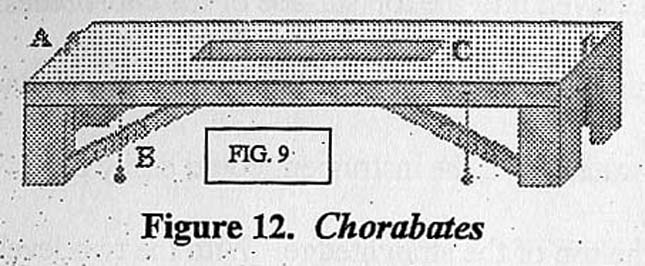
The chorobates had a much simpler design, and unlike its predecessors, could be quickly built without any cumbersome and precision labor. This is the primary reason why historians felt that it was the principle level used to build the famous aqueducts. On the down side, the chorobates was very awkward to use. It was nearly twenty feet long, stood almost five feet tall and was made from solid wood. The stock used to produce the straightedge had to be sturdy enough to prevent sagging of its center, thus creating the awkwardness. A system of plumb bobs were initially used to level the instrument. This was achieved by hanging plumb bobs from the leveled straight edge of the chorobates and scoring the cross-members with a vertical line where the strings crossed on all four corners. This process proved to be very challenging for the Romans because string placement was very critical. If the strings were attached too close to the cross-member, the friction of the two touching one another would throw off the leveling process because the string would not be dangling freely. On the other hand, mounting the strings too far away from the cross-member would cause more error to be thrown into the leveling process because more judgment, by eyesight, would be required. Also, the effect of the plumb bobs, being hung too far away, would leave them susceptible to swaying. For those reasons, Vitruvius added a water level to the chorobates.
The water level was actually a trough carved into the top surface of the chorobates. Water was poured into this trough that measured approximately five feet long, one inch wide and one and one half inches deep. With this water level, the instrument could easily be leveled by getting the water level even with the top of the straightedge. With the two leveling methods in place, the agrimensore used wedges to raise the low side of the instrument until one or, ideally, both of the leveling methods were achieved.
Once level, the chorobates was used to sight a leveling rod. Whether the leveling rod was the one as described above, in conjunction with the dioptra, or was similar to a decempeda, as described later in the linear realm, was not apparent in the research. The combination of the instrument and leveling rod proved to be a fairly accurate method for the agrimensores in the building of Roman cities. Recently, a survey historian replicated a one-quarter scale model of the chorobates and tested it against a modern level in a 51.3 meter leveling traverse. The chorobates' accuracy was found to be 1:1,282.5. This accuracy is not perfect for long distance surveys, but acceptable in the scope of construction.
After researching various pictures, descriptions and dimensions of the chorobates, a student team reached a consensus. The chorobates is to be teen feet long and five feet high. The cross-members will be cut at forty-five degree angles and attached to the legs for additional support of the straightedge. Next, a channel five feet long, 1" wide and one and one half inches deep will be cut out of the top center of the straightedge for the water level. Lastly, four strings, each suspending a single plumb bob, will be placed two per side at opposite ends of the straightedge, and allowed to hang down alongside the forty-five degree cross-members for leveling.
The chorobates needed to be sturdy enough to support its own weight, so the following timbers were used: a ten foot 2" by 10" was used for the straightedge, 2 - 4' oak 2" x 10" beams were used for the legs, and 2 - 5'8" 2" x 10" beams were used for the cross-members.
While using solely dowel pins would be the preferred method of constructing an authentic replica, the student team opted for the use of modern fasteners to construct our chorobates. We used one-half inch by 4" lag bolts to connect the legs to the straightedge. First, a one-quarter inch pilot hole was drilled so that the wood would not split. Next, a three-eights inch hole was countersunk into the straightedge over the pilot hole. The lag bolt was then inserted into the countersink hole and bolted down through the pilot hole. Finally, after all the lag bolts were fastened securely, a three-eights inch dowel rod, to protrude out of the holes one-quarter inch, was cut and secured over the lag bolt with wood glue to give the appearance of using dowel pins for construction. This process was performed for each of the legs of the chorobates. The cross-members were attached in similar fashion, but using 2" exterior screws instead of lag bolts. The holes for the exterior screws were predrilled using a number 33 drill bit, and the countersinking will still be a three-eights inch hole that will fit the dowel rod.
We used an electric router with a 1" drill bit to build the water level into the chorobates. After finding the center of both the length and the width of the straightedge, we scribed a line two and one-half feet from this center point, in both directions, along its length. The router was set to a depth of three-quarters of a inch and used to cut the 5' trough down the center of the straightedge. After cleaning the groove out, a final cut at a depth of one and one-half inches was made into the straightedge. Finally, a beveled chisel was worked in the channel to give the channel a hand-cut look. After the channel was finalized, we applied beeswax to give the channel a waterproof finish.
The sights of the chorobates are made from one-eighth inch flat stock, one-quarter inch wide by 3" long. The flat stock was bent at right angles, creating a sight that is 1" high and 1" long. Two sights were created, one for each opposing end of the straightedge. Two one-eighth inch by one-eighth inch holes, side by side, running parallel with the centerline of the straightedge, were drilled 1" from the end of the straightedge and offset one-half inch from the center. This set of holes created a guide for the sight to be inserted into. Four sets of the holes were drilled to provide placement of the sights. Before the sights were inserted into the holes, we poured vegetable oil into the holes to cause the wood to swell around the inserted sights, thus securing them into place. When the sights were inserted, they were driven deeper into the holes so that they would be one-half inch tall.
Using a carpenter's square, laying flat along the cross-members and extended to the bottom of the straightedge about one and one-half feet from the legs, a line was scribed for the placement of the plumb line. This line was scribed on all four locations of the cross-members. A one-quarter inch hole was drilled one-eighth of an inch out toward the edge of the straightedge from the scribed point. Using a utility knife, a groove was cut into the inside of this hole that will have the hemp string fitted into it. A one-quarter inch dowel rod was cut to the same depth of the previously drilled holes. After tying a knot at the end of the hemp string, we inserted it into the hole while making sure that the string was long enough to extend past the cross-member. Wood glue was forced into the hole, making sure that the hemp string was in the cut groove, and then followed by the insertion of the dowel rod into the hole. This setup allowed the string to hang freely. The weights were then attached to the ends of the hemp string and made sure that assured clear distance between the cross-members and the string was achieved, without compromising the accuracy.
Use of the Chorobates
To begin leveling the chorobates, a flat and level surface is needed. Once the chorobates is on this surface, mark the location of the legs so that this spot can be accurately reproduced. Set two benchmarks straight out from the chorobates at twenty and forty foot increments. These locations will provide the control for the leveling procedure. With a lead pencil, label each leg, one with Roman numeral I, and the other with Roman numeral II. Using the leveling rod and the Roman numeral I leg being the sighting leg, sight the first benchmark and record this reading. Repeat the process for the other leg. Rotate the chorobates 180 degrees, so that the leg designated as Roman numeral II is now the sighting leg. Re-sight both benchmarks. Determine which set of data is lower and this will indicated which leg is higher. Repeat this procedure until the readings match. Once the chorobates is leveled, scribe a line where all four hemp strings cross the cross-members. When these lines are scribed, perpetuate the marks by scribing a wood burn along the length of the scribe line, being careful not to burn the hemp string.
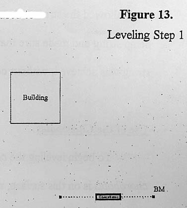
Using the chorobates is similar to the use of a modern-day automatic level. A benchmark (BM) is needed to carry a set of elevations to various points throughout a project. In the following the chorobates will be used to determine the elevation on the four corners of a building.
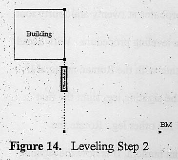
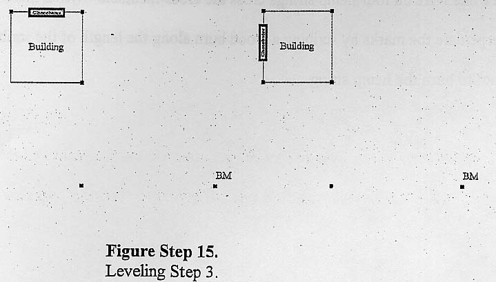
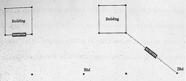
The chorobates is then set up and leveled, so that a line can be extended from the benchmark to a new point that is in line with two corners of the building (Step 1). Next, move the chorobates onto the line, between the new point and the two corners of the building (Step 2). Level the chorobates again and record the elevations taken at these two points. Now, move the chorobates so that it is in line with one of the located building corners and an unknown building corner (Step 3). Use the known corner from the previous step to acquire the elevation of the unknown point. Repeat this procedure until all of the building corners have known elevations. Finally, check back to the original benchmark and check for closure (Step 4).
In light of the results and comparisons found in researching the methods of leveling, the consensus was that the chorobates would be the method of leveling used by our student agrimensores in competition, in addition to its historically intended uses. The University of Akron, due to lack of confirmation on this matter, has taken the liberty of using the leveling rod that was mentioned in conjunction with the dioptra, as the main leveling rod. We believe that this would produce better quality measurements than the use of a linear distance rod.
LINEAR DISTANCE MEASUREMENT
The final category to be discussed is in the area of linear distance measurement. According to our research, the primary method of determining linear measurements was the use of wood measuring rods and pre-stressed ropes. One of the key instruments, used by Roman agrimensores for linear measurement, was called the decempeda (pronounced "dess-em-ped-ah").
The Decempeda
This instrument was primarily used as a linear distance measuring rod, although at times used as a sighting rod or leveling rod. The rod, according to research evidence, was made of hardwood and capped at its opposing ends with a ferrule made of bronze or other native metals. This ferrule was designed so that two rods could be "leapfrogged" by attaching to each other, while butting up against metal caps to create a seamless 20-foot measuring staff. According to many sources, this was the primary method for measuring linear distances.
For example, let us say that an agrimensore wanted to measure, on a flat piece of ground, a straight linear distance of 50 Roman feet. The agrimensore would lay down the first decempeda with the "0" end at the beginning point (Step 1).
Next would be to attach the two decempedas to each other by means of the interlocking mechanism. This would be done by inserting the end of the first decempeda into the hole of the "0" end of the other decempeda, creating the "seamless" twenty foot rod (Steps 2-3).
The following steps (Steps 4-7) demonstrate the "leapfrogging" process of measuring. Once the agrimensore has measured twenty feet, to carry on with his measuring, must remove the first decempeda, while holding the position of the second one, and connect it in similar fashion to the second decempeda.
This "leapfrogging" process is repeated by the acting agrimensore until he achieves the desired measurement of 50 Roman feet.
As a by-product of creating the decempeda, inquiry into what units of measure were used, so as to accurately portray how the decempeda was divided. After careful search and inquiry, the consensus was that the decempeda was 10 Pes, or Roman feet, in length. This works out mathematically to 2.96 meters. Each Pes is equivalent to 296 millimeters. Each Pes was divided into 16 digitus for more acute measurements. Evidence of numbering the divisions on the decempeda and of smaller linear increments than the digitus, was not recovered.
Once the divisions of the decempeda were agreed upon, actual construction was begun. To the best of ability, the recreation of a Roman decempeda was as follows: 2 - 11' pieces of oak, measuring 1" x 3", were fashioned together with nails and wood glue along its length. This creates a 2" x 3" x 11' solid staff for the decempeda. The ends of the staff were trimmed to a length of 9' 8" to accommodate for the copper caps to be attached at the ends later in construction. This length of 9' 8" is the standard conversion from 2.96 meters, which was the agreed upon length of the decempeda. Metal caps were secured to both ends to create a hard, flush surface. This allows the two rods to butt against one another to create a "seamless" 20-foot measuring tool. Two-inch holes were created at one end of the decempeda where the two rods will come together. This hole served the purpose of creating a simple interlocking device to help hold the tow decempedas together. A 2" dowel was fastened in one of the holes. This end is to be inserted into the opposite end of the other decempeda, to create the interlocking mechanism for a "seamless" 20 Pes decempeda. The Pes and digitus increments were scored, by wood burning, onto the decempeda to create permanency of the increments on the face of the instrument. Increments were scored as follows: zero was established at the end of the decempeda, followed by 15 digitus scores, then followed by a 1 Pes score, distinguishable from the digitus markings. This pattern was followed until the end, where a full 10 Pes measurement would be at the opposite end of the rod. Since no evidence of smaller increments were discovered, a "base-10" system will be employed to divide the digitus. A base-10 system is nothing more than taking a known increment, in this case the digitus, and dividing it into ten equal parts. These smaller increments were scored, in like fashion, on a smaller hand-held ruler, not on the actual decempeda proper. This will help keep the increments already on the face from being too cluttered.
By the efforts of research and manpower, it is to be believed that this process is in line with being a proper and accurate method of recreating a Roman decempeda. This method has produced two sturdy, field-worthy surveying tools that will serve its purposes well.
Ropes
The use of ropes as a measuring device does not come implicitly. Hero of Alexandria only mentions ropes in description. Hero describes the process by which the ropes were stretched between stakes or hung with weights to stretch them to proper length. They were then covered in beeswax or tree resin to keep them from shrinking. Rope lengths or divisions can only be speculated, as no evidence exists today. Study of Roman distance equivalents and Roman sighting devices provide the most logical length of rope. The Roman acreage equivalent of one actus being 120 x 240 Roman feet square lend itself to a 120 Roman-foot rope. A rope of this length would be practical for the Roman process of land division known as centuriation, mentioned earlier with the groma. Ropes any longer than this would be difficult to use, as Roman sighting devices were limited to normal eyesight. They did not have telescopes or magnification.
The process by which we re-constructed a Roman measuring rope involves selecting a suitable base material. A commonly found natural fiber twine called jute was selected. Three twine strings were given a flat braid together to produce a single rope. The rope is lightweight yet strong and durable enough to stand up to use. The rope was stretched between two posts for approximately one week. During this time the rope was retightened every twenty-four hours to maintain consistent tension. Next, knots were made at approximate location for Roman Pes. Wooden beads were slid against the knots and a separate short length of twine was knotted to maintain the beads place on the rope. The bead cannot be allowed to move along the length of the rope even when the rope is tensioned. Any movement of the bead would introduce errors into any measurement. The location of each Roman Pes was scored onto the beads while they were tensioned for accurate and consistent measure. The last step involved rubbing pine tar onto the rope surface to limit the amount of shrinkage the rope would exhibit, as well as protect it from the elements. The pine tar was allowed time to set up and solidify while the ends of the rope were knotted and looped for handles. Throughout the process of making the rope, tests were performed to check the ropes accuracy against a steel tape. The tests revealed that although the rope expanded approximately two percent across its length, it still remained sufficiently accurate.
The rope is utilized similar to current steel taping procedures. Wood stakes are used to mark the ends of the rope for measuring distance longer than 120 Pes. Lead-cast plumb bobs were used as well. The rope is used in conjunction with a one-Pes wooden scale that further divides the Pes into 16 digitus units. The rope is often used along with the groma for running lines.
ADDITIONAL RESEARCH
In an effort to maximize our understanding of the surveying methods of the agrimensores, additional information had to be compiled to even begin to grasp the concepts behind the instruments and how they work. It is this additional knowledge that helped us derive the meanings and methods of surveying in ancient Rome. This second part is a comprehensive representation of what was uncovered, in respect to the following additional research: linear and vertical units of measure, the conversions for those units to modern-day units of measure and the surveying terminology of the agrimensores.
The primary focus in our added research was to get a good grasp of what exactly were the different units of measure. In comparing the different sources, and agreement was made as what units were made mention of more throughout the texts. A safe presumption was made, based on the common ground established, that these common units were the true units that the agrimensores used in their work. It is these units, found in "Appendix A", that were applied to our instruments, where appropriate. The charts contained herein, provided by Mike Neill's website entitled "Measures of Length", sum up the agreed-upon units of measure. It was by this comprehensive chart that the decempeda, rope and dioptra rod were carved into its appropriate increments. Many of the conversions to modern-day units were already presented; no further calculations were required. Due to in-depth research, the discovery was made that most historians agree that the Pes (Roman foot) was truly divided into 16 digitus, instead of the once-understood 12 digitus. Several sources confirmed this fact, therefore, it was agreed upon to use 16 digitus as the standard division of the Roman foot. Other conversions that were required during our research were to convert a dactyl to modern units. This is easily represented by the ratio 24 dactyl = 1 cubit = 1.5 feet.
In trying to understand the terminology behind Roman surveying, several websites offered much in the way defining the terms. Excluding those terms that were incorporated into our instrument research, we found these terms to be beneficial in understanding the methods of the agrimensores and placed them in the Glossary. John Peterson's website titled, "A Glossary of Agrimensorial Terms", is where the list of terms that were encountered in our research, were derived.
CONCLUSIONS
This summarizes the efforts and evidence of the University of Akron's student representative to the April 2002 American Congress on Surveying and Mapping/F.I.G. college surveying competition. This paper shows the apparent care that was undergone, by the students, in researching the accuracy of historical accounts and discoveries. This paper also shows the depth of application of the knowledge gained through research by the accurate construction of replica agremensor instruments, as well as their use in ancient surveying and construction. Through research, development of instruments, and understanding how those instruments were used in practical surveying methods, the student representatives feel confident that they will accurately portray how an ancient Roman survey crew would layout any type of parcel or structure common to ancient Roman times.
Appendix A
GLOSSARY OF TERMS
actus: unit of linear land measurement, 120 Roman feet (pedes monetales). This was equivalent to 35.1 - 35.6 meters. The value in common use during the empire was around 35.5m, giving a value of 710m for the side of a century of 20 actus.
Centuriation: a form of surveying (limitatio) in which the limites divide the surveyed land into squares, or, occasionally, rectangles. Centuriations are known of various sizes from 10 x 10 to 20 x 20 actus. During the late republic and empire the centuriation of 20 x 20 actus appears to have been normal.
Century: a square of a centuriation.
decumanus (-i): a limes parallel to the decumanus maximus.
decumanus maximus (DM): one of the two orthogonal principal axes of a centuriation. In the case of the Orange B cadastre the stone tablets (tabulae) shows it running east-west (depicted vertically). By convention, the decumanus maximus is assumed to be the axis more nearly oriented in this direction, but counter-examples exist in reality.
forma(-ae): the base map of a Roman cadastre; also (possibly) the base map of a survey which was not followed by allotment and recording of land holdings. A map or plan, in general.
iugerum(-a): a measure of land (1 x 2 actus).
kardo(-ines): a line parallel to the kardo maximus.
kardo maximus (KM): one of the two orthogonal principal axes of a centuriation, at right angles to the decumanus maximus.
limes(-ites): lines of division (axes) of a Roman cadastre: an area was divided with limites and assigned "within the limites", i.e. within the framework of these cadastral lines, using them to record the operation both on the ground and on the forma. These lines were often, but not invariably, followed by roads or pathways whose breadth and surface treatment varied according their status and function.
terminus(-i): for the Roman land surveyor this was a survey marker, or (more specifically) a stone inscribed with coordinates within the framework defined by the KM and DM. The term may also be used to refer to the supposed position of a terminus, at the corners of the centuries or subdividing the sides.
territorium(-a): the area of land controlled by a Roman town, whether registered in a formal cadastre or not.
Appendix B
TABLE OF UNITS
WORKS CITED
Adkins, Lesley, and Roy A. Adkins. Handbook To Life In Ancient Rome. Fact On File, Inc., 1994
Andy. Virtual Roma. August 2001. 7 January 2002. http://it.geocities.com/mp_pollett/roma-aq2.htm
Australian Defense Force Academy. Assignment 1 An Engineering Marvel of the Ancient World
Aqueducts of Rome. 19 December 2001. 7 January 2002. http://octarine.itsc.adfa.edu.au:8080/~z2280337/ee/ass1.htm
Calvert, J. B. Old Units of Length. 25 February 2001. 29 January 2002. http://www.du.edu/~jcalvert/tech/oldleng.htm
Campbell, Brian. The Writings of the Roman Surveyors Great Britain: Stephen Austin & Sons, Ltd., 2000
Dilke, O. A. W. The Roman Land Surveyors. New York: David & Charles, 1971.
Ingram - Hagen & Co., P.L.C. Virtual Museum of Surveying, 29 January 2002. http://www.surveyhistory.org/roman_glory_hadrians_wall.htm
Ingram - Hagen & Co., P.L.C. Virtual Museum of Surveying, 7 January 2002. http://www.surveyhistory.org/roman_surveying.htm
Institute and Museum of History of Science. Pompeii: Nature, Science and Technology In A Roman Town. 30 September 2001. 7 January 2002. http://galileo.imss.firenze.it/pompei/scienza/index.html
James, Peter and Nick Thorpe. Ancient Inventions. New York: Ballantine Books, 1994
J. Paul Getty Trust. Trajan's Rome: The Man, The City, The Empire. 2000. 7 January 2002. http://www.getty.edu/artsednet/resources/Trajan/PDF/lesson3.pdf
Kentucky Educational Television. How Romans Built Roads. 2001. 7 January 2002 http://www.dl.ket.org/latin3/mores/techno/roads/construction.htm
Kiely, Edmond R. Surveying Instruments: Their History and Classroom Use. New York: Columbia, 1947
Lancaster-Jones, E. 1925. Catalogue Of The Collections In The Science Museum. H.M. Stationary Office, London, pg. 53
Lewis, M. J. T. 2001. Surveying Instruments of Greece and Rome. University Press, Cambridge
Ministry of Culture. Fountains In Ottoman Istanbul. 2002. 12 March 2002. http://www.kultur.gov.tr/portal/tarih_en.asp
Neal, John The Roman Measures. 2000. 29 January 2002. http://www.secretacademy.com/pages/romanmeasures.htm
Neill, Mike. Measures of Length. 4 March 2001. 29 January 2002. http://romantables.8m.com/length.html
Nineteenth Yearbook of the National Council of Teachers of Mathematics. 1947. Bureau of Publications. Teachers College, Columbia University. New York. pg 35.
Peterson, John. A glossary of terms used in Roman land surveying. 4 April 1996. 7 January 2002. http://www.sys.uea.ac.uk/Research/researchareas/JWMP/glossary.html
Romano, David Gilman. Information about the Corinth Computer Project. 2 October 2000. 7 January 2002. http://corinth.sas.upenn.edu/corinth.html
Stone, Edward Noble. Roman Surveying Instruments. Seattle: Washington Press, 1928.
|
|
|