![]()
![]()
![]()
|
|
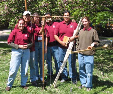
ROMAN ERA SURVEYING Compiled by: New Mexico State University - Roman Surveying Team
Abstract The National Society of Professional Surveyors (NSPS) has created a surveying student team competition to be held at the joint American Congress on Surveying and Mapping (ACSM); American Society on Photogrammetry and Remote Sensing (ASPRS); and Federation Internationale de Geometres (FIG) annual spring conference in Washington, D.C. on April 23, 2002. In accordance with the guidelines directed by NSPS, we (a team of six surveying engineering students from New Mexico State University) have reproduced two roman surveying instruments: the Groma, and the Libra. The following report entails the documentation of the research conducted and surmised to create the aforementioned roman surveying instruments.
The military and monetary power of the Roman Empire enables their society to build an infrastructure of roads and water systems responsible for the sustenance and propagation of a society lasting hundreds of years. At the heart of roman civil engineering projects was the Roman surveyor. He was an integral part of the building of this great empire. Unfortunately, the written history of the methods and tools of the Roman surveyors have long since been lost with time. There are no field books or explicit manuals explaining the daily computations and surveying techniques of the Roman surveyor. In addition, there is little archeological evidence of the use of properties of surveying instruments used by the Roman surveyors. Much of the modern day understanding of how the Romans surveyed is based on conjectures from a small amount of evidence.
Archaeologists and historians have had to piece together their own versions of Roman era survey instruments by speculating on the various metal part found in archaeological sites of Pompeii and the rest of the former Roman Empire. The only verifiable depiction of surveying instruments has been found on tombstones like that of Lucius Aebutuis Faustus. The Corpus, a collection of manuscripts from Roman surveyors assembled into a manual of survey instructions provides insight into the practice of surveying, but does not describe the instruments used. The writings of Heron of Alexandria describe a wonderful multi-axis surveying instrument called the dioptra, but ther is no evidence to suggest that the Roman surveyor adopted its use.
At one known excavation in Bavaria, an iron cross was discovered with a hole at the intersection of the arms. At the end of the four sections, there were holes with the remains of iron nails. It is speculated that this particular artifact had a wood frame around the cross as well as a wood base and the iron nails were used to hang a plumb lines. This find is the subject of debate as to whether or not it is an instrument; some contend it to be a groma while others think it an agricultural implement. In 1912, on an excavation in Pompeii, Della Corte discovered the office of a Roman surveyor named Verus. The metal parts of a groma were found along with other instruments such as poles and measuring rods. Della Corte's reconstruction of the groma has become the standard image of what this type of instrument looked like. Recent research has disclosed that the parts Della Corte assembled into his instrument were found in several different locations, suggesting that his reconstruction is not a very accurate one.
What is known from these sources is that the groma was the most common instrument used during the Roman period and it served as the primary surveying instrument used by the Roman surveyor. The design and principle of the groma is straightforward. The groma consisted of 2 arms (approximately 3 feet in length) crossed at the middel, one being perpendicular to the other. These arms were attached to a swinging bracket. This bracket was attached to a wooden staff offsetting the groma for greater ease of use. At the foot of the staff was the ferramentum, an "iron foot" having four large flukes or wings for stability purposes, and a sharp tip on the end of it. This served as the base for the staff. From the end of each of the four arms hung a plumb bob or a cord. There was a fifth plumb bob that was attached to the, umbilicus soli, the center of the crossed arms. This was used to located the instrument over the point from which observations were to be made.
The groma was limited to sighting, setting out straight lines, and right angles. The surveyor worked only in the horizontal plane with this instrument and was not concerned with differences of height. The surveyor sighted diagonally across one pair of cords to project a straight line or to set a perpendicular line to the line defined by the other pair of plumb bobs. This simple instrument was well suited to surveying road alignments, establishing the gridwork of roads and streets for towns and military camps, and above all, for rectangular land subdivisions. The one shortcoming due to the groma's simplicity was that wind played havoc with the plumb-bob strings, making it very difficult to survey on blustery days.
Leveling instruments are not mentioned except by name in any of the books of the Corpus. The name libra aquaria appears several times throughout the texts. This has traditionally been interpreted as being a water level, some instrument filled with water to define a level surface. A recent approach has interpreted this term as a level for laying out watercourses, specifically for aqueducts. Another form of level called the chorobates, meaning "land walker", is well described in Vitruvius' (an architect) text. This was an instrument 20 feet lone, with plumb line levels at each end and a groove along the upper surface to be filled with water. It is not mentioned in the surveyor's texts and appears better suited to maintaining grade during construction rather than for differential leveling.
The Egyptians and Greeks of the era are known to have used a rope marked off in increments to measure distances. The Roman surveyor apparently did not. There are references in the Corpus of using cords for alignment while measuring, but not for the act of determining the distance. What the Romans used were ten feet long wooden rods with metal ends. These rods, called pertica, were laid end to end along a course of survey to determine the total distance. While much slower, this method was more accurate than the use of the rope, because the poles did not give erroneous measurements due to stretching and contracting. Specialized methods for measuring horizontal distances were developed. Steep sided valleys too wide to measure across in the ordinary way were measured by an operation known as cultellatio. The surveyor would hold a ten-foot rod horizontal with one end resting on the ground at the beginning of the slope. At the other end of the rod the surveyor would drop a plumb line and mark a point where it hit the ground. He then moved the end of the rod to this point still horizontal and repeated the first step continually going down the slope and up the other side to the point of ending, measuring the horizontal distance.
The Romans used a somewhat different unit of measure than that of modern times. The Roman foot, which is 11.65 modern inches, was divided into 16 inches rather than the modern division of 12 inches. The Roman foot consisted of four palms of four Roman inches, where a palm is about 3 modern inches. The Roman mile consisted of 1000 paces, or 5000 Roman feet. There are four values of feet and stades, which were used, quite often in Hellenistic and Roman times:
When performing layouts, the square was the most common area. The smallest square area was known as a scripulum, which was 10 Roman feet by 10 Roman feet. The next largest area was known as an acnua, which was made up of 120 Roman feet by 120 Roman feet, or 1 actus by 1 actus. An iugerum was rectangular area comprised of acnuas, and then a heredium was simply 2 iugerum. The largest square was defined as a centuria, which is 2,400 feet by 2,400 feet, or 20 actus by 20 actus. This is comprised of 10 heredium by 10 heredium.
Given the above research, we determined to recreate enough Roman era survey instruments to be able to perform leveling, lay out right angles, prolong a line and measure distances. We selected the groma, the libra and the pertica as being capable of performing the tasks presented at competition. We also accepted the Roman survey foot as 29.6 centimeters and constructed all instruments to dimensions in those units. In keeping with the technology of the time, all iron parts have been hand forged, the wood pieces finished with linseed oil, and the plumb-bobs cast from lead (plumbium is Latin for lead, hence the term "plumb line").
The design of the measuring rods was essentially a given; two wooden rods ten Roman feet long with iron tips, graduated in even feet except at each end where the first/last foot was split into 16 digits. A spool of twine is used to provide alignment while measuring longer distances. The other instruments are based upon our interpretation of the evidence found.
Recognizing that the authors of Roman archaeological history texts have not been surveyors, and the difficulties associated with translating Old Latin into modern English, we have made some unique interpretations of our own. The Corpus makes mention of the groma in text, but more often refers to its base, the ferramentum, when describing its use in survey. We decided that the ferramentum was analogous to our modern tripod, being the foundation for the instruments that level and provide alignment. Therefore it had to be short enough to sight over so we built it at five feet tall instead of Della Corte's suggested two meters. The actual point on the lower end is of four blades to provide stability like the base that Della Corte did find. The upper end has a threaded pin that will accept both the groma and the libra. A plumb line is built into the shaft to indicate verticality.
The arms of our groma are about three feet long, with lead bobs at each end suspended by plant fiber strings. The instrument is set on an offset hinged bracket with another suspended bob that is used to assist in setting up the instrument directly over a point or line.
Our libra is six feet long with wooden slits for sights. It balances on the threaded pin atop the ferramentum and is weighted for stability with a matched set of plumb bobs. One of the pertica is used as a leveling rod, but with the addition of a movable target. The instrument operator provides alignment, while the rod person takes the readings. To assist the survey during windy days, a screen of cloth is used to shield both the libra and groma from the disturbing currents of air.
BIBLIOGRAPHY
Roman Land Surveyors O.A.W. Dilke' Newton. Abbot, David & Charles, 1971
Surveying Instruments: their history E. R. Keily. Columbus, Ohio, Carben Surveying Reprints, 1979
Greek and Roman Technology K. D. White. Ithaca, New York, Cornell University Press, 1984
The Writings of the Roman Land Surveyors - Introduction, Text, Translation and Commentary Brian Campbell. Great Britain, Stephen Austin & Sons Ltd., 2000
Surveying Instruments of Greece and Rome M. J. T. Lewis. Cambridge, UK, Cambridge University Press, 2001
Antepasados Surveyors in History Wilfried E. Roeder, P.S. Albuquerque, New Mexico, New Mexico Professional Surveyors, 1995
|
|
|